Site Owners
Pilots
Download our app below to start discovering new landing sites


This article explores the several types of take-off profiles available to helicopter pilots and aims to provide guidance on what is the most appropriate technique for the specific obstacles around the site, what the performance and power requirements are for each type of profile, and review at the difference between single and multi-engine helicopters.
We will look at a range of helicopter operating site examples and explore incidents when the pilot was unsuccessful in safely taking off, looking at the common causes of why the accidents occur.
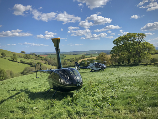
Being able to land and departing from confined, off airfield, locations are the main advantage held by helicopters over cheaper, faster, equivalently sized fixed wing aircraft. During initial PPL training, a large amount of time and effort is spent on trying to teach pilots about limited power exercises, using techniques high and low reconnaissance overflights, and employing the ‘5S’/ ‘4W’ aid memoir when assessing landing areas to be able to utilise this ability safely.
The take-off profile and technique used to depart depends on several factors: the number of engines on the helicopter, the type or class of operation, the space available, and the obstacles around. Whilst the space in front of the helicopter is obviously important, for multi engine helicopters, the pilot needs to consider the area behind, as the take-off profile operating in a tight area or an elevated helipad involves going slightly backwards and upwards, so if there’s any problem it can land back on the helipad.
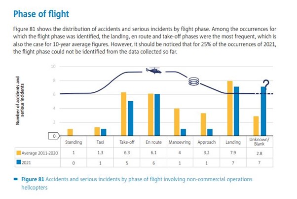
Unfortunately, analysis from the EASA helicopter safety team puts the proportion of accidents during take-off as 17%, and including approach and landing, this rises to 45%. Over a 10-year period, EASA assessed just under 9 take-off accidents per year from ‘non-commercial’ helicopter operators.
During take-off, several key factors come into play, including power management, weight and balance, wind conditions, and environmental considerations. Loss of control can result from a combination of these aspects, including pilot error, mechanical failures, and adverse weather conditions. It is the first phase of flight where these issues may be recognised.
Mechanical Failures:
Helicopters are complex machines with many critical components, and mechanical failures such as engine malfunctions, flight control restrictions or gearbox issues present themselves during the high power, initial flight phase, which can lead to catastrophic accidents during take-off. Detailed pre-flight checks are essential to minimize this risk.
This video provides an example of a power failure during takeoff with an EC130.
Irrespective of the ‘profile’ used, during take-off, you are inevitably at a high-power setting, low airspeed and low height above the ground, which gives limited reaction time for the pilot, and potentially means operating in the height velocity diagram where a safe autorotation is not possible.
Weather Conditions:
Adverse weather conditions, including strong winds, turbulence, fog, and poor visibility, can significantly increase the risk of accidents during take-off. Later in the article, we will review an accident that occurred when the pilots took off into thick fog, when they were unwilling to delay or cancel the flight despite the weather conditions.
Weight and Balance:
Proper weight and balance are critical for safe helicopter operations. The first a pilot often learns about an improperly loaded helicopter, is when it becomes unstable during take-off, and inadequate cyclic control authority exists to stabilise the hover, leading to a loss of control. Check the weight and balance limitations and conduct thorough pre-flight checks.
Power Management:
Helicopters require careful power management during take-off. Insufficient engine performance once the helicopter moves out of the ground cushion, or failure to adjust power as altitude and airspeed change can result in accidents. Performing a power check before committing to a take-off profile prevents pilots from being caught out.
Collision with obstructions
Human error is a significant contributor to helicopter accidents, and misjudging clearance to obstacles is a common factor. Unsurprisingly, during take-off and landing, you are in the closest proximity to other ground obstacles. The internet is awash with examples of pilots that have collided with all sorts of obstacles during take-off, ranging from trees, lighting poles and, in the example below, a parked truck.
Rotor disk collisions can often be attributed to this visual illusion of the apparent rotor disk size against the real dimensions. The pilot is sitting forward of the centre of the rotor disk, so the amount of rotor disk visible ahead of the cockpit only represents a proportion of the total rotor diameter. The mistake Is when the pilot applies this ‘reduced rotor’ diameter to their situational model of the helicopter and the surroundings, and the helicopter blade clips an object, usually with catastrophic consequences. The way to counter this error is to look at the rotor tip path plane either side of the helicopter, to correctly estimate the clearance to objects. This is the subject of a safety video from Claude Vuichard
The tail rotor remains the most vulnerable part of the helicopter, due to lack of direct visual reference to it from the cockpit. For any hover manoeuvres that you have to perform, repositioning for take-off in a confined area, ensure that ‘all turns are around the tail’, to keep the helicopter clear.
Whilst in this video, the pilot got extremely lucky due to the shrouded tail rotor design of the fenestron on the EC120 (and other airbus/ Eurocopter designs), the result of a rotor strike is usually disastrous for the helicopter.
The video in this report provides a stark reminder of the challenges when landing ‘off airfield’ don’t stop the moment you land. As the pilot, you are responsible to ensure that the area around the helicopter is clear from the public, who may often act illogically when presented with the noise and excitement of a helicopter taking off. If you are departing from a site that is easily accessible to the public, such as a restaurant or hotel, try and enlist the help of the local management to keep a safe cordon away from the helicopter whilst the rotors are turning.
Downwash and Recirculation
When landing in a tight landing site, vegetation and trees are blown away from the centre of the downwash, increasing the clearance from the rotor disk and the obstacles. Unfortunately, on take-off, as soon as you start producing lift from the main rotor, you induce an airflow downwards, from above the rotor disk. In practice, this means that whist you might be able to land in a tight spot, getting out might be more problematic, as trees and overhanging vegetation bend inwards, towards the centre of the rotor disk, reducing the top clearance. This may have been one of the contributory factors in this Bell 407 rotor strike when climbing vertically away from some trees.
Recirculation is the phenomenon of the downwash from the rotor being redirected upwards, and then back into the rotor disk by an obstacle or building outside the rotor tip, such as when hovering close to a hangar. Not only does circulation reduce hover performance, due to the increased ‘induced flow’ reducing the angle of attack, and therefore lift produced, for any given collective setting, but when recirculation occurs unevenly around the rotor disk, this adds further piloting challenges. Cyclic correction will be required to adjust for the uneven lift production across the rotor disk, and left unchecked, there is a risk of the helicopter unintentionally drifting towards the obstacle. It is one of the reasons that hovering in front of, or between two large buildings requires more piloting input.
Insufficient training, experience and incorrect technique:
Lack of currency, experience, and incorrectly flown ‘take off’ techniques are a common issue among many pilots, where insufficient knowledge and experience can lead to poor decision-making and mismanagement during take-off. Use your regular recurrent training and proficiency checks as an opportunity to practice more advanced manoeuvres under the protection of an instructor.
EASA has published the lesson plans for the PPL, exercise 28 and 29 refer, if you want a little more revision.
Unintentional Yaw
Unintentional yaw, often described as loss of tail rotor effectiveness (LTE), has been attributed to many accidents during the take-off or landing phase. LTE is often associated with the prevailing wind interacting with the main rotor vortex, tail rotor vortex, or providing weather cock instability as a result of pressure on either side of the vertical stabiliser/ fin.
This EASA safety video provides a good explanation on the topic.
This Airbus FlightPhysics Web Application provides a further interactive explanation and demonstration of how insufficient pedal application can catch unwary pilots out. If confronted with an unexpected yaw, the solution is to apply full ‘opposite spin’ pedal, try and maintain the helicopter in a level attitude, and wait for the spin to stop. Then you can correct with the other pedal, bringing the helicopter back under control.
Ground Resonance
Ground resonance can occur on a helicopter with 3 or more blades and can be induced when the centre of gravity of the rotor disk doesn’t line up on the axis of rotation. Whilst it can be triggered by mechanical issues, such as blades of unequal weight, or faulty blade dampers, it can also occur when taking off from spongy, soft ground, which can allow the helicopter to start to rock or move in symphony with the motion of the aircraft.
The options, in the event of this developing, is to quickly lift into the hover, if sufficient RPM exists, or shut the engine down and apply the rotor brake as quickly as possible.
The videos below give an idea of how quickly it can develop, and how destructive the situation can be:
Dynamic Rollover
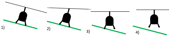
Unfortunately, sometimes things go wrong before you have even got yourself set up for the actual departure take-off. Whilst a dynamic rollover accident isn’t limited to confined areas, the threat is often increased due to sloping, uneven, soft ground. It can occur when one skid gets stuck in the mud, hooked on an obstacle, or is firmly iced to the surface.
The key to a smooth takes off is taking things slowly:
There is an old pilot mantra: ‘Slow is smooth, smooth is fast’.
Treat any off airfield landing as a sloping ground take-off- and at the slightest inkling of dynamic roll over, lower the collective, as no amount of lateral cyclic will stop the helicopter from pivoting over.
The pilot in command must be responsible for the operation and safety of the aircraft and for the safety of all crew members, passengers and cargo on board.
Annex VIII Part NCO.GEN.105
Checking that the performance of the helicopter is sufficient is a basic requirement before you take off.
Simple reminder, if operating in hot, high or humid conditions, you may be performance limited on take-off!
The performance factors which significantly affect take-off are:
Compliance with these rules can be achieved by using the performance data graphs contained in the RFM. Use the graph and trace the applicable data to determine the performance capabilities for the given conditions – and then confirm those values with the applicable in-flight power check applicable for helicopter type. Flight Manuals have graphs for determining density altitude, IGE and OGE hover ceilings, take-off distances, and rate-of-climb performance.
EHEST – Helicopter Performance HE12, Section 2.1
Whilst most of these factors seem obvious, aspects such as the surface type impacts how much ground effect you can expect to benefit from, with long grass, water, or crops absorbing more energy, thus reducing the advantage compared with short grass, asphalt, or concrete. A slope also reduces the positive impact as the ground cushion will dissipate down slope.
Whilst in many cases, you don’t need to obtain permission to take off from an off-airfield location, if the site is located within controlled airspace, you need to obtain a clearance first. Line of site radio communication may not be possible, so take note of the phone number for the controlling ATC agency and give them a call beforehand. Like a radio call, they will want basic details of who you are, what sort of helicopter, where you are lifting from, where are you going, intended routing, time of departure, and possibly number of persons onboard.
In return, they may give you a clearance, both in terms of altitude and a routing, a transponder code and ask to call on a nominated frequency in the low hover, or if radio communication can’t be established, call as soon as possible in the initial climb.
If you don’t get clearance before you take off, either by radio or over the phone, the authorities will consider this as an ‘airspace infringement’, with all the additional paperwork that this entails – so don’t forget!
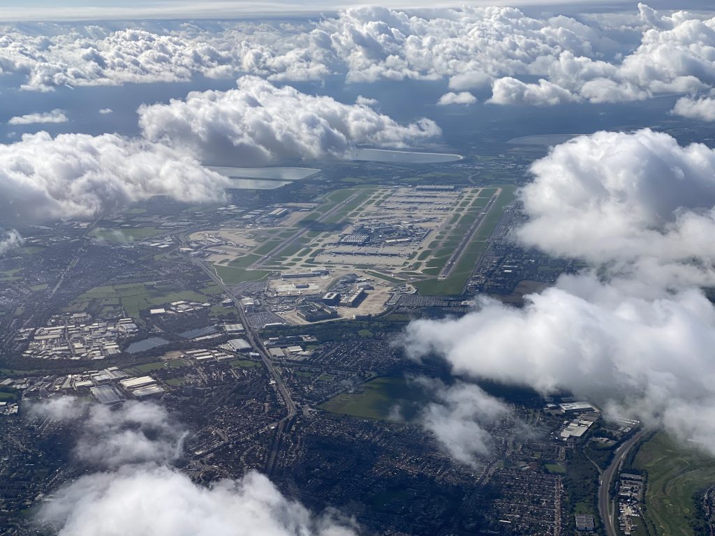
Some locations, such as London, have further complications to the above procedure. The area around Heathrow airport is known as the ‘inner area’. To operate in this area, the pilot needs to call the ‘Senior watch Assistant’ of the London Terminal Control Zone, 60 minutes before the take-off or landing to get PPR approval code. Further details can be found on the national AIP. In the case of Heathrow, this can be found under section 11 of the EGLL entry.
Low Flying Exemption
The authorities provide exemptions from the low flying rules to permit helicopters to take off and land, however in November 2023, the UK CAA (CAP 2613) clarified that it interprets the ‘take-off and landing phase’ to be the final stage of an approach, or the initial stage of departure, when the helicopter is in a stable flight configuration, at or below 500ft, AGL, and the area surrounding the FATO is clearly visible.
During the approach to land at a site, the high (1000ft) and low (500ft) reconnaissance provides the pilot with a good awareness of the surrounding terrain and obstacles, and you would usually identify a clear ‘escape route’, in the event of a missed approach, which usually coincides with the obvious take off direction (either because it is into wind or it provides the clearest exit away from obstacles).
However, when the helicopter is shut down in the confined area, perhaps overnight, or after an extended period, where conditions, such as the wind direction, speed and air temperature have changed, it is good practice to perform a ‘ground reconnaissance’ on foot, before departure, to determine a take-off point and assess the optimal take-off direction.
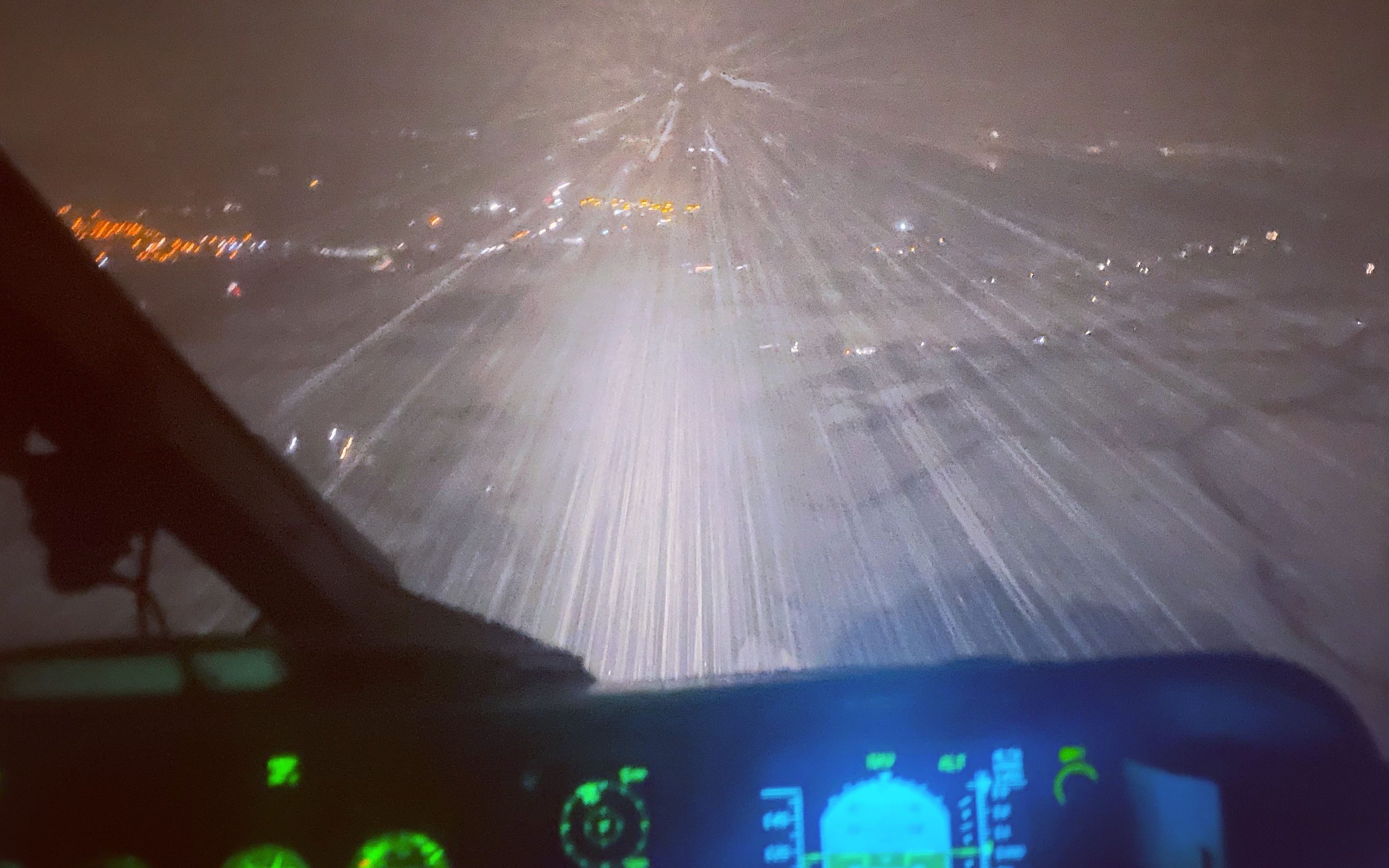
The pre flight preparation should obviously cover the weather conditions along the intended route. Take-off into poor conditions can rapidly lead to disorientation, especially if the helicopter is ‘unstable’ at low speed, and close to the ground.
The accident in this report occurred when the helicopter took off into thick cloud and the pilots failed to monitor the height during the manoeuvre.
Another accident which occurred in 1998 to a police Twin Squirrel helicopter lifting at night encountered fog at low level during the transition to forward flight resulted in loss of control.
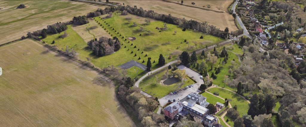
The site guides held on Helipady are a fantastic aid to pre identify preferred routes and possible obstructions. Similarly, using aerial photographs, such as ‘Google Earth’ or ‘Bing maps’ can be incredibly helpful to build situational awareness, and establish rough distances to obstructions, especially if there is 3D data, but there is no substitute to walking around, evaluating the wind direction and speed.
It allows you to look at the effect of the wind within the confined area, establishing if there are areas that are blanketed by the wind, that then cause wind shear as you clear the any obstructions, or areas of potential turbulence behind buildings or trees.
The direction of wind, relative to your departure path is important to understand, as coming out of a site surrounded by trees or high obstacles that blanket the initial climb, you can suddenly find yourself inadvertently downwind, with a sudden increase in power requirement and yaw pedal requirement to prevent weathercocking around the tail.
This simultaneous application of ‘power pedal’ and raising the collective can droop the rotor rpm, especially in a turbine engine. This in turn, exacerbates the situation – the loss in RPM decreases the lift produced (lift is proportional to the square of the relative velocity of blades), both in the main rotor and the tail rotor, and the pilot then raises the collective further to try and maintain altitude – increasing the drag, and further reducing the RPM.
This cycle continues until the engine ‘catches up’ with the power requirement, increasing the fuel flow, drawing more air in, and increasing the power produced. If the initial power application, and subsequent further raising of the collective is too abrupt, especially in a power limited environment, an overpunching event occurs, usually with the helicopter ending up on its side near the departure point.
During this thorough ‘recce’ of the site, identify hazards, obstacles and the sun position. This review might dictate whether the take-off direction might be altered.
With this information, you can decide on the safest, most advantageous point to commence take-off, ideally providing the maximum available distance for the take-off profile and selecting a departure route. You can also decide on which forward and lateral reference points can be used as markers during any positioning during take-off, so that you know in advance that the tail and main rotor have sufficient clearance from obstacles. Example of poor position control or situational awareness when operating in a confined space:
The pilot should establish the climb out path from the operating site by asking ‘what is the safest way out of here?
If the operating site is surrounded by obstacles, then the vertical climb technique should be used. However vertical climbs which necessitate prolonged periods in the shaded area (avoid area) of the HV diagram should only be used when necessary.
We will go through each type of departure profile in detail later, but you need to decide on the type of profile required, to then check the performance available on the day. If there’s plenty of space available, a transition takes off, accelerating forward before climbing uses less power and therefore allows for more fuel or payload to be carried than a vertical departure.
Before we review with the different power requirements for take-off techniques, firstly we need to cover the two certification categories for helicopters: either certified to CAT A, or CAT B Standard.
A helicopter that is certified to CAT A is the capable of sufficient performance for either safe landing or safe continued flight if you were to lose an engine during take-off, whilst CAT B helicopters do not provide this performance, either because they only have one engine or because the remaining engine is not powerful enough, and so a forced landing will occur .
The normal single engine helicopter take off profile is designed to keep you out of the dead man’s curve, the height velocity diagram that is published in the flight manual, which shows you at what altitude and speed combinations a safe auto rotational landing may be achieved if correctly flown.
The H/V envelope is the combination of height and airspeed from which a safe landing in case of an engine failure cannot be guaranteed because of the overall aircraft energy balance.
The H/V diagram in the Rotorcraft Flight Manual depicts the boundary of the height and speed envelope where actual successful landings, after engine failure, have been demonstrated during certification test flights.
Within the H/V envelope (the shaded/hatched zone), a successful landing, in case of an engine failure, has NOT been demonstrated and CANNOT been guaranteed.
Bruce Webb
Below is the height velocity diagram for the Robinson r 66 turbine, single engine helicopter, and shows the recommended take-off profile, used in a clear area. All H/V diagrams include a recommended take-off profile, which must exceed the HV curve by at least 5 knots.
The hatched area on the left of the diagram covers the situation where you’re at low speed or an out of ground effect hover, but not sufficiently far high off the ground, so that an auto rotation may not be successful. This is because you won’t have enough height to accelerate the helicopter sufficiently and then flare before you impact the surface.
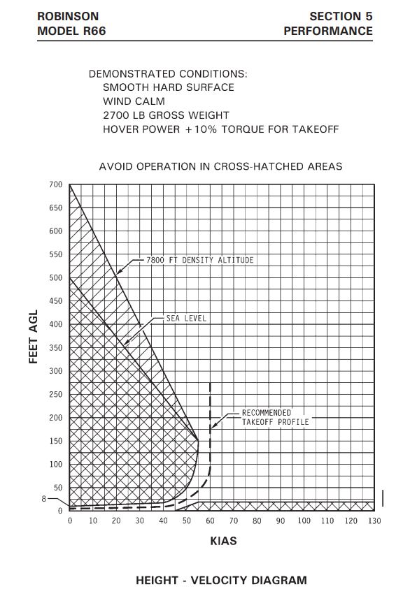
In the event of an engine failure, the pilot has 3 sources of energy to utilise to enact a safe landing.
Once you’re high enough, you have enough time to convert potential energy from height into speed and safely land in the event of an engine failure.
Pilots try and minimize their time flying these two areas of the graph to increase their chances of safe landing, if there is a critical engine malfunction however sometimes it is unavoidable, either because the confines of the operating site, or because of the type of operation which they are performing, for example in sling load operation or powerline inspection.
During helicopter type certification, the manufacturer produces a ‘height velocity diagram’ which considers the various areas of stored energy in the rotor head, and the average pilot’s reaction time to an engine failure.
“A superior pilot is one who uses their superior judgment so as not to have to use their superior skills.”
Anon
To understand how the HV diagram is established, we have to recap some basics. In auto rotation, the rotor rpm is a function of 3 main factors when weight and environment conditions are kept constant –
1)Airspeed – all other factors the same- for a constant collective pitch setting, the higher the airspeed, the higher the rpm
2) Disk loading – increasing the disk loading- i.e. by pulling the nose up and increasing the g force/ apparent weight of the helicopter – increases the rotor rpm (such as what happens during the flare manoeuvre). Decreasing the disk loading, by lowering the nose initially decreases the rpm.
This relationship is often demonstrated during flight training during autorotation practice manoeuvres- climbing up a few thousand feet, once established in an auto at around Vy/ 60kts , rotor rpm in the middle of the green band- collective pitch set – and not touched for the rest of the manoeuvre – the helicopter attitude is pitched up- the rotor rpm goes to the maximum , due to the flare, however, as the airspeed drops off , so does the rpm – decreasing back to the middle of the permitted range . Once at 0 kts airspeed, then pitch the helicopter attitude down, to accelerate the airspeed.
Initially rpm decreases to the minimum due to the low airspeed and unloading of the rotor, but then as the airspeed builds, the rpm goes back to the middle of the range. You can perform the full airspeed / disk loading relationship on the descent without needing to touch the collective, just managing the rpm by modulating how quickly the manoeuvre is performed)
3) Collective pitch – keeping airspeed and helicopter mass the same, the higher the collective pitch, the lower the rpm
To establish the top left side of the HV curve, consider a helicopter in an out of ground effect hover, which then suffers an engine failure.
The first thing that happens is the rpm decays. The inertia of the rotor system is the only thing keeping the rotors spinning. The heavier the helicopter, or the lighter the blade, the quicker the RPM reduces.
The next action from the pilot is to lower the collective- this reduces the blade pitch, reducing the lift , but also the drag, so the rotor rpm stabilises within a preset range (it is critical to prevent a critical decay of rotor rpm to such a slow, unrecoverable value, where they can stall) , and allows more of the rotor blade to enter autorotative ‘driving’ state, which, like a sycamore leaf or auto-gyro, produces both the lift that reduces the rate of descent and keeps the rotor blade turning.
During the flight testing, to simulate the reactions of an ‘average pilot’, the test pilot has to wait a second before lowering the collective.
Next, the nose is lowered to allow the helicopter to build speed, effectively taking it outside of the ‘shaded area’ – moving the helicopter further right on the graph.
In practice, a pilot will often both simultaneously lower collective, accelerate and adjust the trim (anti torque pedals). By accelerating, you then are increasing airspeed, giving you more options for range / landing sites, reducing the rate of descent, but also adding additional kinetic energy that can be used for the flare when performing the landing, permitting a lower touch down speed / reduced rate of descent.
Obviously, sitting in a hover, then lowering the collective rapidly, and simultaneously pointing the nose at the ground is going to make the rate of descent rather high, the top of curve is sufficiently heigh above the ground- to permit you to accelerate from the hover to best autorotation speed and descent while rotor RPM recovers sufficiently for a safe landing.
If you are within the shaded area of the curve, lower to the ground, then you won’t have the ‘time’ – i.e. height above the ground, to sufficiently initially manage the rpm and accelerate to the best autorotation speed , and compromise instead with a lower airspeed prior to starting the flare manoeuvre, which may not result in a successful landing due to the higher rate of decent, which wasn’t arrested during the shorter flare.
A flare with higher initial airspeed can be maintained for longer, reducing the rate of descent and forward airspeed of the helicopter prior to touchdown (increasing the chance of a successful outcome)- because there is more kinetic energy from the forward motion that helicopter could be converted to kinetic energy of the rotor disk- i.e. in the flare the rpm is kept high for longer.
Height above the ground is critical- you need sufficient height to convert into airspeed, to then be able to flare before hitting the ground. The very top of the curve- 0 speed and 500 ft above the ground in the case of the R66, is the worst-case scenario – the minimum height to go from 0kts, accelerate to optimal autorotation speed, then land.
Any airspeed above 0kts, at that same height, is an improvement on the situation for a pilot.
If you are at the same height, but already holding some airspeed, you have a ‘surpluses of time- i.e. it will take less time before you have accelerated to the optimum airspeed for autorotation.
In terms of the HV diagram, during flight testing, it means that there is ‘more’ than the minimum height for that airspeed/ height / weight combination, so the test pilot then tries the manoeuvre again at a slightly lower height to see if the autorotation can be carried out successfully, thus building the various points along the curve.
For certification, the tests have to be carried out at maximum take-off weight, at for conditions of sea level, and up to 7000ft density altitude (some manufacturers plot multiple curves, others rely on the pilot interpolating between the two data sets, depending on the operating conditions- i.e. , if you are less than the maximum weight at sea level, the curve will be smaller than what is published, but if you are operating at max weight above 7000ft , the avoid curve is bigger!) .
The certification tests also must be carried out onto a smooth, hard surface, without the benefit of any headwind, and no permanent damage or deformation is permitted, even to the skids. Whilst in testing, the helicopter can be run on at any speed, the reality of many emergency situations is that the landing surface may not be large or smooth enough to permit anything other than a slow walking pace may not be conducive to a safe touchdown!
Whilst the 1 second delay after entry is there to replicate the initial reaction a normal pilot has, bear in mind that the test pilot clearly has the edge on alertness and general handling practice. They also know precisely when the engine will fail, have practiced, and prepared for their immediate actions, based on each test point required for the HV curve plot, and do not need to worry about the selection of a suitable landing location. In other words, they have an advantage as they induce the loss of power, having fully prepared, not caught unaware by it, which translates to a disadvantage to the average pilot in reality!
Bruce Webb, the former Airbus USA chief pilot, has a 4-part series on the HV diagram that is well worth a watch.
Some key points from him are summarised below:
Timely recognition of the emergency and proper entry into the autorotation are key to a successful outcome, an area which may need improvement and where training efforts should focus.
Use all the training tools available: if you do not have access to a simulator, practice the recognition and glide segments in the helicopter as often as necessary, but always within gliding distance from a suitable landing area.
A good entry is critical and sets the scene for a good touchdown.
Practice doesn’t make perfect, but it certainly improves the odds.
Prior to the departure from an operating site, a power margin calculation from the RFM may be required as may a hover power check as a confirmation to establish the exact power margin available. Special attention should be paid to the re-calculation of C of G, weight and loading if passengers/ cargo or fuel has been off loaded or uplifted.
These performance limitations are of key importance when operating at high elevation, especially on hot and/or humid days.
Engines produce less power in hot weather and at high altitudes, and therefore, the energy available to accelerate the helicopter varies with atmospheric conditions.
Additionally, for the same temperature and altitude, a heavy helicopter requires a longer take-off distance, and for the same mass, take-off at a hot or high site requires greater distance of clear space ahead.
Similarly, for the same temperature and altitude, a heavy aircraft will have a lower rate of climb, and, for the same mass, the maximum rate of climb in hot and high conditions is less.
This obviously has serious implications when flying a helicopter on a hot summer day, or up in the mountains, where passengers, baggage or fuel needs to be offloaded before take-off, especially if you are planning to operate out of a confined area or operate from a pad with high elevation surrounds, where you might not be able to out climb the rising terrain.
Remember HOT, HIGH and HUMID and if any of these apply ensure that your performance calculations are accurate.
Most performance-related accidents can be prevented, provided that the pilot maintains a good awareness of the surrounding conditions, knows the performance limitations of the helicopter, always does a power check before committing to a marginal situation, and is disciplined enough to ‘give it away early’ if the odds are stacking up against getting the job done safely. Before each confine or remote landing, carry out a power check to ensure you have appropriate horsepower – remembering that flight manual performance data can be optimistic.
NZ CAA Helicopter Performance
Effects of High Altitude and C of G outside Limits
Remember, The allowable range of CG positions for most helicopters is incredibly small. For the AS350 Squirrel helicopter, the total permitted range is only 32 cm!
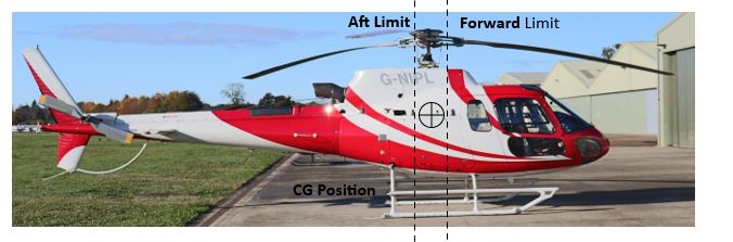
Even the Super Puma large passenger helicopter only has a longitudinal CG range of 50 cm, with a lateral permitted CG range of just 17 cm.
The limits of CG are dictated by the amount of available control authority. So, if you fly outside the CG range the consequence is partial or complete loss of control.
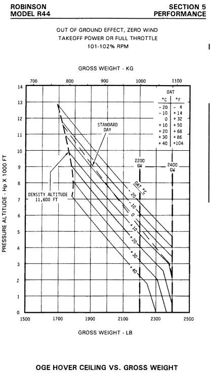
An R44 helicopter with 3 persons onboard was departing Courchevel heliport on the last day of a mountain training trip in March 2008. The heliport is orientated on the side of a mountain at 2000m (around 6600ft), where these is only one approach or departure path, meaning that either the take-off or landing will be at least partly downwind. Unfortunately, the high-density altitude reduced the power available, and the helicopter crashed when attempting to transition away due to encountering turbulence and then having insufficient power to recover. Fortunately, the 3 occupants survived. The below extract from the R44 Raven 1 flight manual shows that a high-density attitude day, caused by relatively low pressure, high temperature and elevation can really reduce the hover performance. Reciprocating engines, without the benefit of super chargers or turbochargers (which are not fitted to any helicopter currently in production), lose around 25% of their power capacity when going from sea level up to 10,000ft due to the air density reduction. Whilst the rotor profile power decreases due to the density reduction, there is an increase in induced power- as the less dense air must be accelerated to a higher velocity in order to produce the same thrust as it would at sea level.
The French BEA report on the event can be found here.
Even with ‘standard’ pressure and 10 °c OAT, the OGE limit drops to approx. 2060lbs, 340lbs short of the maximum approved take off weight.
AW109 Overloaded
In December 2014, involving damage a twin engine AW109 helicopter, occurred when a VIP flight attempted to take off overloaded in Dubai. Commercial pressure was a major factor when additional, unweighted passengers boarded the helicopter during a stressful uncoordinated ‘rotors running’ boarding process. The take-off weight had not been calculated correctly (the helicopter attempted to take off above the maximum certified take off mass) and the maximum passenger number had been exceeded. The helicopter didn’t have the performance to clear the helipad area, and landed heavily onto a road, causing the landing gear to collapse and the tail rotor to contact the ground.
R44 Fatal Loss of Control
A fatal accident occurred in January 2018 when an R44 was destroyed on impact into a residential area in Newport Beach, California, a minute after take-off. The American NTSB evaluated that the helicopter was operated above the maximum gross weight, and, had the flight continued, the CG would have ended up outside the forward limit as fuel was burnt off from the main tanks. The probable cause was determined as the pilot’s failure to perform weight and balance calculations before flight, and the subsequent loss of control shortly after take-off.
The normal sequence for take-off and departure from an operating site should be as follows:
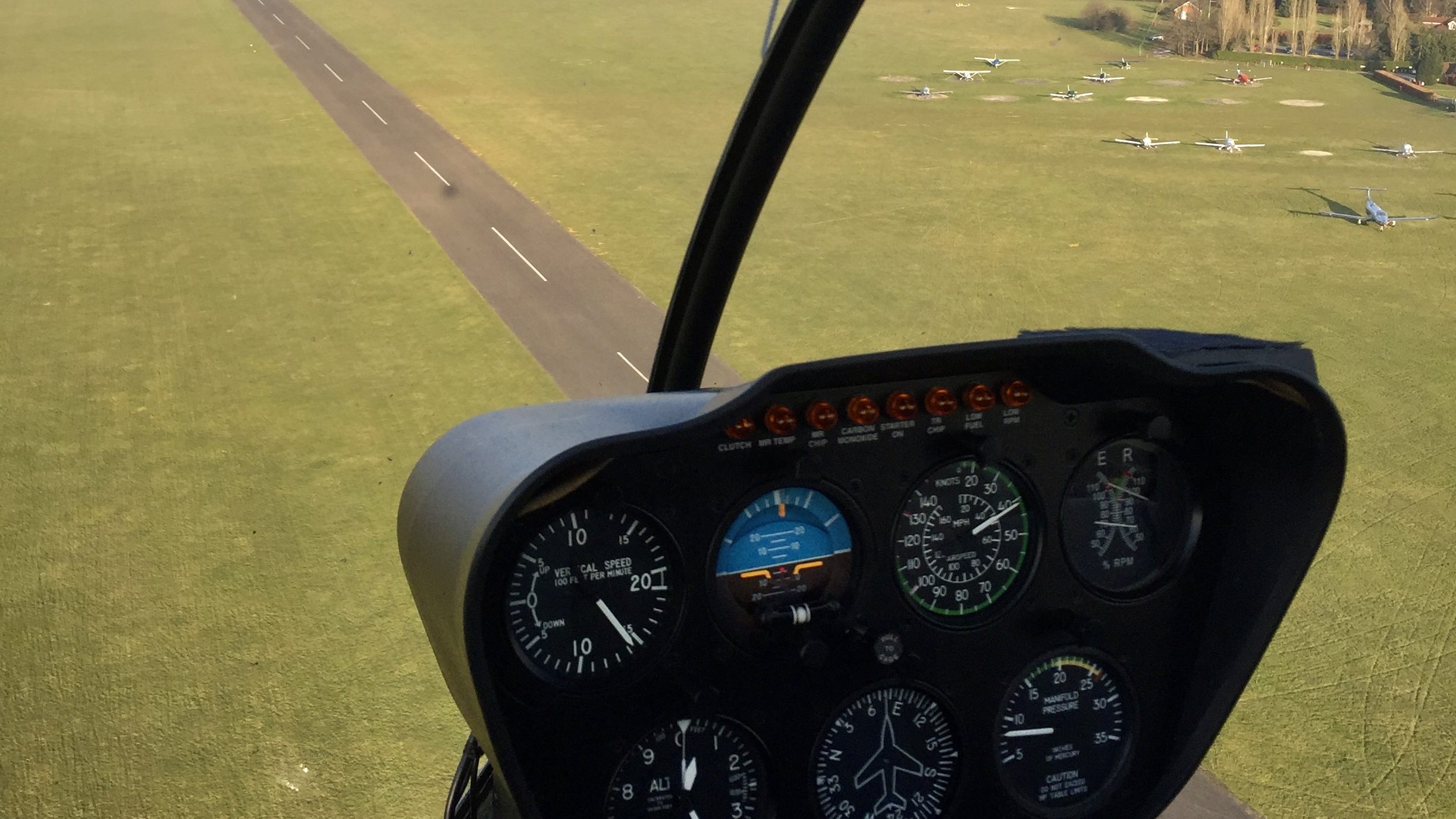
A thorough lookout is necessary when lifting from the confined area, especially for any aircraft that are overflying/arriving/departing the landing site, whom may not be in radio contact, in contrast to when flying out of an airfield,
A ‘normal transition’ using best available Rate of Climb should be flown wherever possible- this gets you clear of obstacles as quickly as possible, minimises noise disturbance to anyone on the ground (a key part of flying neighbourly), and the additional hight gives you more options in the event you have a critical engine malfunction. ‘Backtracking’ to the rear of the landing site may make extra distance available for the transition.
Before take-off, if the helicopter has a range of acceptable RPM limits, increasing it to the top of the green band will provide the maximum power for take-off. Power is proportional to the cube of the RPM, so a difference of just 3% increases the power available by almost 15%. Some helicopters automatically increase the RPM for this reason at slower speeds, such as the EC130, where the lower RPM in cruise helps to minimise the noise signature.
A fatal accident occurred in January 2018 when an R44 was destroyed on impact into a residential area in Newport Beach, California, a minute after take-off. The American NTSB evaluated that the helicopter was operated above the maximum gross weight, and, had the flight continued, the CG would have ended up outside the forward limit as fuel was burnt off from the main tanks. The probable cause was determined as the pilot’s failure to perform weight and balance calculations before flight, and the subsequent loss of control shortly after take-off.
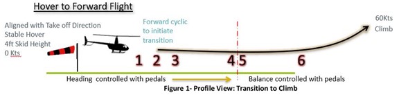
Using an example of a Robinson R66 helicopter,following the recommended normally take off profile from an airfield- this is the simple transition from the hover to forward flight, where space is not at a premium.
| Stage | Effect | Pilot Action |
| 1 | The pilot applies forward cycle to initiate transition to forward flight. Loss of Height as rotor disc is tilted, and total rotor thrust is angled away from the vertical, with a forward component of thrust causing helicopter acceleration | Raise Collective to increase total rotor thrust to compensate |
| 2 | Flap Back | Apply further forward Cyclic to maintain the same accelerative, nose down attitude |
| 3 | Inflow Roll to the right (advancing side of the rotor disc) | Apply Left Cyclic to maintain level and prevent roll |
| 4 | Transitional Lift (between 10-20kts) | Move the cyclic further forward to continue helicopter acceleration, preventing the helicopter from climbing |
| 5 | Yaw Left due to increase tail rotor effectiveness as it moves through translational lift | Right Pedal to reduce the anti-torque reaction- As airspeed increases, the vertical stabilizer starts to produce an anti-torque reaction, further reducing the required tail rotor pitch angle |
| 6 | Obtain safe climb out speed (55-60kts) | Aft cyclic input to raise the helicopter attitude and initiate a climb |
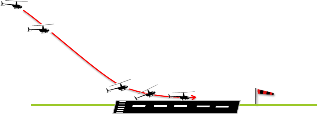
The helicopter starts in a 4 to 6 ft hover and smoothly accelerates as it transitions to forward flight. Around 40 knots, after passing through effective translational lift, you raise the nose, and the helicopter starts to climb continuing to accelerate to around 60 knots which is usually close to the best rate of climb speed (VY). In the highly unlikely event that there an engine failure during take-off then an immediate emergency landing is required so the area ahead of the helicopter should be clear of any obstructions that might prevent a safe landing.
When obstacles such as buildings, trees or power lines, in front of the helicopter prevent you from accelerating, before climbing, a maximum performance take off is required.
This manoeuvre requires more power to complete when compared to a normal take off, so you need to check the helicopter performance, to ensure you can safely hover ‘out of ground effect, for the given helicopter weight, air temperature and pressure altitude of the day.
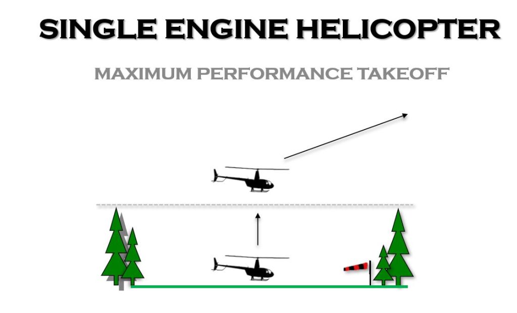
This technique requires you to climb the helicopter vertically until you clear the height of the obstructions trees or buildings before accelerating forward. You can expect the benefit of the ground cushion up to around ½ the height of the rotor diameter, so in an R44, this is around 17 ft or 5 meters. Some pilots have been known to enter a higher hover, slowly descend, compressing the ground cushion and then applying max power, like bouncing on a trampoline to use the inertia upwards to improve the climb rate in the OGE hover! In the book, ‘Chickenhawk’, by Robert Mason, he describes a situation in Vietnam when an overladen Huey inadvertently lands in a minefield. Lacking the power to clear the barbed wire fence, right pedal (‘non-power’ pedal) was used to transfer power from the tail rotor to the main rotor to provide just enough extra thrust to clear the fence. I don’t recommend getting yourself into a situation where you need to use this trick though!
When doing this manoeuvre, its crucial to select visual markers that you can always see from within the cockpit. This will stop you from accidentally drifting into these obstacles. It also means if you find out that you don’t have enough power to climb, you can always safely descend back to where you started knowing that it is clear. Once you have safely cleared the height of the obstacles, the nose is gently pushed forward to accelerate into normal flight.
It can often be difficult to correctly judge just how much nose down attitude is required- clearly too much could lead to loss of height and into a sticky situation, too little and the acceleration will be painfully slow, increasing your exposure time within the HV diagram. A good trick is to look at the rotor disk tip path plane in the hover, with reference to a fixed point in the cockpit or the horizon – for example the top of the instrument panel. For the acceleration, reduce this distance by half. This also works when taking off from a mountain top, where the illusion of the ground rushing away below you, despite the limited forward airspeed, can be disorientating.
For a multi-engine helicopter, the take-off profiles are similar, but there are is the inclusion of a key point during the process, where a decision is made to either continue to take off or to abort if there was an emergency. in a helicopter it’s known as the ‘take-off decision point’, TDP and its similar to the ‘v-1’ speed and a fixed-wing aircraft.
The clear air departure for a CAT A multi engine helicopter is very similar to that of a single engine helicopter: accelerating through translational speed close to the ground before climbing. The only difference is the inclusion the take-off decision point.
The pilot must accurately fly the take-off profile to hit the take-off decision point (TDP), which is a combination of speed and height above the ground. If you correctly fly that profile, if the space available is sufficient, and the helicopter is operating within the correct weight and performance limits, the take-off is said to be as operating with a Performance Class One.
This is considered the ‘highest standard’ of safety in a helicopter flying, as, in the event an engine failure before the take-off decision point there’s a sufficient remaining engine performance to bring the aircraft back to a landing in the space available. The downside of a clear area take-off is that a lot of space is required- 270m in the case of the EC145 for example, which makes its use limited in most ‘helicopter only’ operating sites.
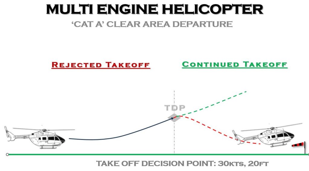
The twin engine Airbus EC135 or EC145 has a clear area TDP of 30 knots and 20 feet.
Once you pass through the TDP, if the engine then fails after this point, the correct technique is then to climb at the take-off safety speed known as VTOSS, which in the EC135 or EC145, is 45 knots and climb up to 200 feet using the maximum power of the remaining engine. This should give you a rate of climb of at least 100 feet per minute
The VTOSS speed is slower than the maximum rate of climb speed (Vy) but you achieve the VTOSS speed quicker than if you were to continue accelerating to VY, and therefore you can start to climb quickly, getting away from any dangerous obstacles.
Once you obtain 200 feet, it is assumed that you are now safely away from any immediate obstacles, and you can now perform a level acceleration up to Vy and reset the power setting to a lower level and continue the climb up to a thousand feet above the ground. At this optimum climb speed, the helicopter should climb at least 150 feet per minute!
If you watch a helicopter take-off from a helipad, either at ground level or on top of a building, you will see commercially flown twin engine helicopters performing a ‘CAT A VTOL’ vertical take-off and landing profile. There are different variations, depending on the helicopter and the surrounding obstructions, but commonly it requires the helicopter to lift upwards and backwards, before transitioning away, once past through the take-off decision point. This TDP is at a set height above the ground, 120 feet for example in the EC145, at which point while still climbing, the nose is lowered slightly and the helicopter flies away.
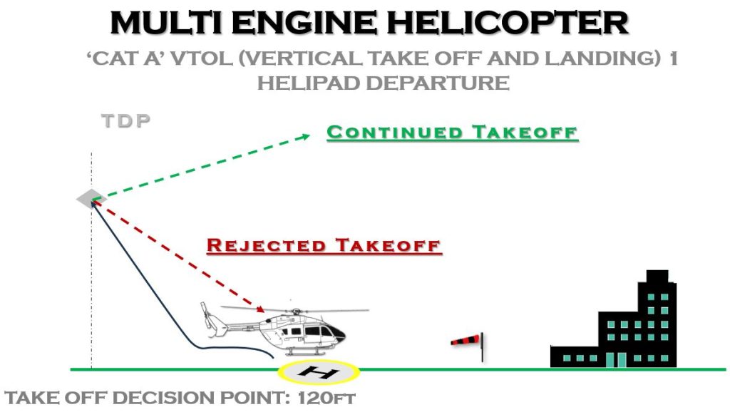
In the event of an engine failure before the TDP, you lower the nose and gently descend back to the helipad starting point, however if the engine fails after the TDP point, you quickly lower the nose (up to 20° nose down) and try and build up speed towards VTOSS whilst accepting the height loss as a trade-off.
The profile is designed to ensure that you’re still clear of any obstacles on the ground during this acceleration phase.
Variations on this profile exist for some helicopters- for example, on the Airbus EC135 and EC145 the ‘VTOL2’ profile is used if there’s an obstacle behind you but some space ahead, so you go straight up, not backwards, and the ‘VTOL3’ is used if there’s obstructions ahead and behind, so you go straight up, then continue going up and backwards.
The difference between certification standards and performance class (PC) is often mistaken. The helicopter is certified to CAT A or B standard, but performance classes relate to what the pilot does on the day. To operate performance class 1, the helicopter has to be certified to CAT A standard, but you still have to correctly fly the designated profile be within certified altitude, temperature and weight limits for the it, and ensure where you are operating from is large enough and suitable for any rejected take-off or climb away.
Performance class 2 is where you fly Performance Class 1 however at some stage during the take-off on landing an engine failure may result in a forced landing. It allows you to carry a bit more fuel or passengers if the operating area has a suitable place to land safely.
Performance class 3, which applies to all single engine helicopters, means that if you lose an engine at any stage of the flight a forced landing will occur. Any commercially operated PC3 helicopter has to ensure that a safe forced landing can be carried out, so max performance take offs with paying passengers is out the question under the UK CAA or EASA rules.
How do you know you have enough power to take off, what is a power check and what is the difference to a power assurance check?
A ‘power check’ should be conducted before committing to the take-off. The first section of a power check is the ‘theoretical’ power, using the flight manual, as discussed in the earlier section. The second section, like on landing, is to check what you actually have, comparing the power used in the hover, sitting in ground effect, against the maximum take-off power available to you for the given environmental conditions.
Finally- the power assurance check, which is included in some turbine powered helicopters is an engineering or maintenance trend monitoring function. It doesn’t serve any practical value when evaluating if you can get in and out of a certain confined area but allows you to track any degradation of the engine health, over time.
You want to take off from a tight area, you have checked that the performance figures say you should be able to hover out of ground effect, given the environmental conditions, but how do you check this before committing to the manoeuvre?
The power check and what gauges you compare against depends on the helicopter you are flying.
In the piston powered R22 or R44, a power check is carried out by first checking the power chart, usually mounted above your head, and confirming what is the maximum power allowed. Then, see what power you are pulling in the hover. Compare the two manifold air pressure (MAP) numbers to evaluate the power margin.
The following ‘rules of thumb’ can then be used:
If the difference is:
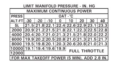
So, as an example, say that pressure altitude is around 2000ft, with an OAT of 20 degrees. The maximum take-off power for the day is 22.3 + 2.8= 25.1, well short of the red line at 26.1.
To hover, you are pulling 23.6 inches. You have just enough power to perform an OGE hover and climb vertically out of the site.
On turbine helicopters, such as the Robinson R66 or Bell 206, torque is usually the limiting factor at lower, colder altitudes. A general guide is that 10% more torque is required to hover OGE than IGE, so if you are pulling less than 90% to hover in the R66, you should be able to perform a max performance take-off.
For the Guimbal G2 Cabri, the power check can be carried from the low however, noting the power % amount. The power margin is the difference from maximum to the actual.
The following margins can be used to estimate the expected performance:
<4%- running take off
4% to 6%- cushion creep,
8% to 10% – Max performance takeoff
For the power check, and during the T/O manoeuvre, ensure that high power consuming devices are switched off. Examples of these include turning the carb heat off on carburetted engines, and turning off air conditioning, or, on turbine helicopters, switching off any bleed heating or anti ice bleed air, if it Is safe to do so.
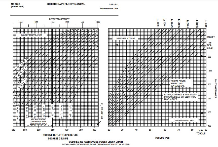
On the MD500, for example, the following graph is provided to confirm the engine is providing the power that it ‘should’. In straight and level flight, you record the parameters of the engine RPM, turbine outlet temperature, and the atmospheric conditions of temperature and pressure. This then gets plotted to see if ‘your’ engine is running too hot for the given torque setting, which, if the case, indicates that you may not meet the performance criteria shown in the flight manual.
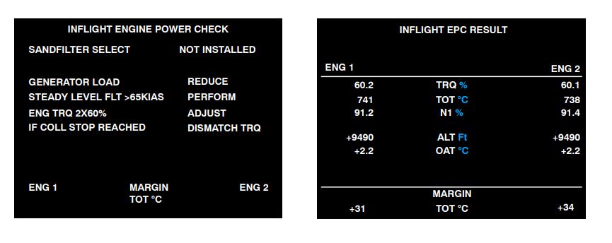
On some helicopters, the engine power check can be completed ‘automatically’, such as on the EC130 and EC135, and usually performed every 50 to 100 hours.
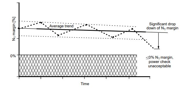
The below is an example of the graphic plot of the engine performance and the acceptable margins, used to detect when an engine starts to underperform.
There are obvious benefits of having a second engine, in the unlikely event of a failure, however, these are a number of disadvantages too, which helps to explain why the majority of helicopters are single engine.
The most obvious is the cost, both in terms of purchase, but increased maintenance costs, and additional fuel burn. When designers are choosing the engine power required for a multi engine helicopter, they have to weigh up the benefits of ensuring sufficient single engine power in an emergency situation vs carrying around an engine that is effectively not fully required for all other flights.
Whilst not wanting to re-ignite the debate that occupies many internet forums on single vs multi engine chat, there are other implications too. Having a second engine doesn’t protect you from any other failure of a critical component (e.g. flight controls and anti-torque device), and there are arguments that the VTOL take-off profiles expose you to an unrecoverable situation for longer, compared with a clear area, accelerative take-off.
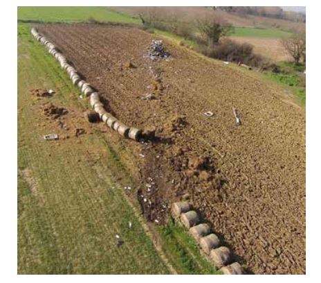
An example of this is the tragic accident of an AW169 which crashed on take-off from an enclosed site, due to a mechanical failure of the tail rotor control, just at the point of accelerating forward from a vertical take-off.
From the AAIB Report
“The congested area permission for operations at the King Power Football Stadium required a Cat A departure to mitigate the risk of engine failure.
The helicopter moved forward and then began to climb out of the stadium on a rearward flightpath while maintaining a northerly heading and with an average rate of climb of between 600 and 700 ft/min. Passing through a height of approximately 250 ft, the pilot began the transition to forward flight by pitching the helicopter nose down and the landing gear was retracted. The helicopter was briefly established in a right turn before an increasing right yaw rapidly developed, despite the immediate application of corrective control inputs from the pilot. The helicopter reached a radio altimeter height of approximately 430 ft before descending with a high rotation rate. At approximately 75 ft from the ground the collective was fully raised to cushion the touchdown.
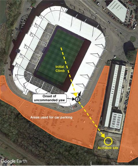
The helicopter struck the ground on a stepped concrete surface, coming to rest on its left side. The impact, which likely exceeded the helicopter’s design requirements, damaged the lower fuselage and the helicopter’s fuel tanks which resulted in a significant fuel leak. The fuel ignited shortly after the helicopter came to rest and an intense post-impact fire rapidly engulfed the fuselage.”
The investigation report concluded:
“The pilot’s yaw control pedals became ineffective after the [Tail Rotor Actuator] control shaft detached, resulting in the pilot being unable to control the direction or rate of yaw of the helicopter.”The pilot’s yaw control pedals became ineffective after the [Tail Rotor Actuator] control shaft detached, resulting in the pilot being unable to control the direction or rate of yaw of the helicopter.
Without effective yaw control the pilot was unable to control the horizontal trajectory of the helicopter.
Cross-coupling of forces generated around the helicopter’s normal axis by the high yaw rate, led to large deviations in pitch and roll.
Simulator trials confirmed to the investigation that the loss of yaw control was irrecoverable.”
AAIB Report to G-VSKP
If you want to learn more, the following are recommended reads:
Shaun Coyle’s Little book of autorotation’s.
Chris Taylor Test pilot
Dick Sanford Review of landing accident:


